THE MECHANISM OF AN ELECTRIC TRAMCAR: THE OVERHEAD SYSTEM
A rough idea has already been given of the elementary mechanism of
electric traction—the combination of generating station, of cars fitted
with electric motors, and of a sliding contact between the two. It is in
connection with the sliding contact that the ingenuity of tramway
engineers has been mainly exercised. Three distinct solutions were
evolved for tramway work, giving rise to three systems—(1) the overhead
or trolley system; (2) the conduit system; and (3) the surface-contact
system.
The first system is now almost universal in the United Kingdom. Part of the London system is equipped on the conduit system; and the tramways at Lincoln and Wolverhampton are constructed on the surface-contact system. Beyond these cases the trolley holds the field. In the United States and on the Continent there is a larger proportion of conduit work, but from a practical point of view it would hardly be necessary to mention either conduit or surface-contact if it were not for the great engineering interest which they possess and for the controversies to which they have given rise.
The overhead system has conquered because it is cheapest in first
cost, cheapest to maintain, most economical in current, and most
reliable in action. Later developments in surface-contact traction have
run it very close on some of these points, but have not—for reasons
which will be explained—affected the established position of the
overhead system.
In its essential features the overhead system has not altered very much from the experimental line erected at the Paris Exhibition of 1881. The slotted tube has been replaced by a solid copper wire; and the 'boat' sliding within it has been replaced by a wheel or a bow pressed against the lower side of the wire by means of a pivoted arm controlled by springs. The sliding bow is common on the Continent, but it has been adopted on only one British tramway—that at Sheerness. Its use for electric traction on railways will be mentioned later, but as far as British tramways are concerned the bow is the exception which proves the trolley wheel rule.
The function of the trolley wheel is to collect current from the wire along which it rolls. This current passes through insulated wires down the trolley arm to the controller, which the driver of thecar operates by means of a handle. The controller, which is really a series of electrical resistances, is analogous to a water tap. By its means the current may be completely shut off from the motors, or allowed to flow in varying degree as required by the speed of the car. In starting a car, the driver moves the controller handle notch by notch, so as to get a uniform rise in speed until the full current is allowed to pass through the motors. With such a mechanism, supplemented by brakes, the driver has the movements of the car under control.
In a four-wheeled car, each axle is driven by a motor. In a bogie car (one with a set of four wheels at each end) the axles of the larger wheels of the bogie are each driven by a motor; but not directly. Considerations of space make it necessary to keep the motor as small as possible, but if a motor is to be small and also powerful it must rotate at a high speed. On the tramcar, therefore, the motor drives a small toothed wheel which drives a large toothed wheel fixed to the axle, thus effecting a reduction of speed between the motor and the wheel.
The same considerations of space join with others in making two motors on each car the general rule. And the use of two motors enabled the tramway engineer to introduce a refinement into the method of control. This refinement is known as the 'series-parallel system.' One of its objects is to give a large 'starting torque' and so enable the car to gain speed quickly. When the current is first switched on by the controller it passes through the motors in tandem or in 'series,' thus dividing the pressure of the current (analogous to a 'head' of water) between them. The starting torque of a tramway motor (or the turning moment which it exerts when current is first passed through it) is dependent on the current but independent of the pressure. Thus the tandem or 'series' arrangement, which passes the full current through each motor, gives the maximum starting torque without an undue consumption of current. After the car is well started, the next movement of the controller puts the motors in 'parallel,' opening up two paths for the current instead of one, so that each motor receives the full pressure. The practical result is that there is a very rapid acceleration at starting, with marked economy in current. If the motors were kept in 'parallel' right through, twice as much current would be required to get the same starting torque. It will be seen later how valuable this arrangement for getting a rapid start, without excessive current consumption, may be in improving the physical and economic conditions of a tramway or train service.
After having passed through the motors and done its work, the current is led to the wheels of the car and returns by way of the rails, which are linked together by copper bonds so as to form a continuous conductor. The passage of the current from the wheel to the rail is indicated by sparks when the rails are rough or very dry and dirty. Although the rails, like the overhead wires, are thus carrying current, there is no danger of shock from them, as the electrical pressure in them is only a few volts, at the outside, while the pressure in the overhead wires is 500 volts. It is this difference of pressure which—like the 'head' of water in a turbine—supplies the motive power for the car.
Each car on a tramway system may thus be regarded as a bridge which completes an electrical circuit. When the driver moves his controller, current flows from the generating station at a high pressure, passes through the controller, operates the motors, and returns to the generating station at a low pressure. This typical circuit is completed through every car, so that the demand on the generating station at any moment is the sum of the demands of the cars at that moment. The business of the engineer at the generating station is to maintain the electrical pressure in the overhead wire at the normal level of 500 volts; and in order to do this on an ordinary tramway system it is found convenient to divide the overhead wire into half-mile sections, each of which has a separate main or 'feeder' from the generating station. The passenger can detect the change from one section to another by the click of the trolley wheel across the gap which insulates one half-mile section from another. At the same spot he can see the short square 'feeder-pillar' at the roadside (containing the switches by which current can be turned off from that section) and the cables which pass along the arm of the trolley standard and terminate in the overhead wire.
On an extensive tramway system the power-supply arrangements become more complicated. The central generating station remains the primary source of power, but sub-stations are erected at convenient points between the central station and the outskirts of the tramway area. These sub-stations are secondary stations for the distribution of electricity. They receive power at extra-high pressure (5000 volts or more) from the central station; they contain special machinery for reducing the pressure to 500 volts for distribution to the various tramway feeders. The object of this arrangement is partly technical but mainly economical. Electric power can be transmitted at a lower cost in mains and with less loss of energy at high pressures than at low. Consequently when the termini of tramway routes are several miles from the generating centre, greater all-round efficiency is secured by transmitting current at high pressure to a number of well selected sub-stations.
The first system is now almost universal in the United Kingdom. Part of the London system is equipped on the conduit system; and the tramways at Lincoln and Wolverhampton are constructed on the surface-contact system. Beyond these cases the trolley holds the field. In the United States and on the Continent there is a larger proportion of conduit work, but from a practical point of view it would hardly be necessary to mention either conduit or surface-contact if it were not for the great engineering interest which they possess and for the controversies to which they have given rise.
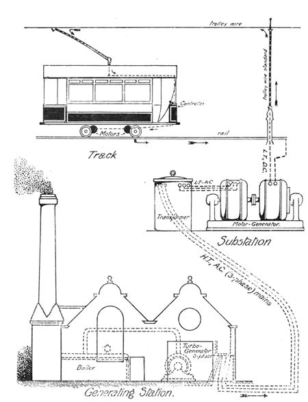
Fig. 3. Diagrammatic illustration of the general
arrangement of an electric tramway on the overhead system. At the foot
is shown the generating station which supplies alternating current at
high-pressure (for economy in transmission) to a sub-station where it is
'transformed' to low pressure and 'converted' in a motor-generator to
continuous current for distribution to the trolley wire from which each
car takes its current. The course of the current through the trolley
pole and controller and thence to the motors and back by the rails is
indicated by arrows.
In its essential features the overhead system has not altered very much from the experimental line erected at the Paris Exhibition of 1881. The slotted tube has been replaced by a solid copper wire; and the 'boat' sliding within it has been replaced by a wheel or a bow pressed against the lower side of the wire by means of a pivoted arm controlled by springs. The sliding bow is common on the Continent, but it has been adopted on only one British tramway—that at Sheerness. Its use for electric traction on railways will be mentioned later, but as far as British tramways are concerned the bow is the exception which proves the trolley wheel rule.
The function of the trolley wheel is to collect current from the wire along which it rolls. This current passes through insulated wires down the trolley arm to the controller, which the driver of thecar operates by means of a handle. The controller, which is really a series of electrical resistances, is analogous to a water tap. By its means the current may be completely shut off from the motors, or allowed to flow in varying degree as required by the speed of the car. In starting a car, the driver moves the controller handle notch by notch, so as to get a uniform rise in speed until the full current is allowed to pass through the motors. With such a mechanism, supplemented by brakes, the driver has the movements of the car under control.
In a four-wheeled car, each axle is driven by a motor. In a bogie car (one with a set of four wheels at each end) the axles of the larger wheels of the bogie are each driven by a motor; but not directly. Considerations of space make it necessary to keep the motor as small as possible, but if a motor is to be small and also powerful it must rotate at a high speed. On the tramcar, therefore, the motor drives a small toothed wheel which drives a large toothed wheel fixed to the axle, thus effecting a reduction of speed between the motor and the wheel.
The same considerations of space join with others in making two motors on each car the general rule. And the use of two motors enabled the tramway engineer to introduce a refinement into the method of control. This refinement is known as the 'series-parallel system.' One of its objects is to give a large 'starting torque' and so enable the car to gain speed quickly. When the current is first switched on by the controller it passes through the motors in tandem or in 'series,' thus dividing the pressure of the current (analogous to a 'head' of water) between them. The starting torque of a tramway motor (or the turning moment which it exerts when current is first passed through it) is dependent on the current but independent of the pressure. Thus the tandem or 'series' arrangement, which passes the full current through each motor, gives the maximum starting torque without an undue consumption of current. After the car is well started, the next movement of the controller puts the motors in 'parallel,' opening up two paths for the current instead of one, so that each motor receives the full pressure. The practical result is that there is a very rapid acceleration at starting, with marked economy in current. If the motors were kept in 'parallel' right through, twice as much current would be required to get the same starting torque. It will be seen later how valuable this arrangement for getting a rapid start, without excessive current consumption, may be in improving the physical and economic conditions of a tramway or train service.
After having passed through the motors and done its work, the current is led to the wheels of the car and returns by way of the rails, which are linked together by copper bonds so as to form a continuous conductor. The passage of the current from the wheel to the rail is indicated by sparks when the rails are rough or very dry and dirty. Although the rails, like the overhead wires, are thus carrying current, there is no danger of shock from them, as the electrical pressure in them is only a few volts, at the outside, while the pressure in the overhead wires is 500 volts. It is this difference of pressure which—like the 'head' of water in a turbine—supplies the motive power for the car.
Each car on a tramway system may thus be regarded as a bridge which completes an electrical circuit. When the driver moves his controller, current flows from the generating station at a high pressure, passes through the controller, operates the motors, and returns to the generating station at a low pressure. This typical circuit is completed through every car, so that the demand on the generating station at any moment is the sum of the demands of the cars at that moment. The business of the engineer at the generating station is to maintain the electrical pressure in the overhead wire at the normal level of 500 volts; and in order to do this on an ordinary tramway system it is found convenient to divide the overhead wire into half-mile sections, each of which has a separate main or 'feeder' from the generating station. The passenger can detect the change from one section to another by the click of the trolley wheel across the gap which insulates one half-mile section from another. At the same spot he can see the short square 'feeder-pillar' at the roadside (containing the switches by which current can be turned off from that section) and the cables which pass along the arm of the trolley standard and terminate in the overhead wire.
On an extensive tramway system the power-supply arrangements become more complicated. The central generating station remains the primary source of power, but sub-stations are erected at convenient points between the central station and the outskirts of the tramway area. These sub-stations are secondary stations for the distribution of electricity. They receive power at extra-high pressure (5000 volts or more) from the central station; they contain special machinery for reducing the pressure to 500 volts for distribution to the various tramway feeders. The object of this arrangement is partly technical but mainly economical. Electric power can be transmitted at a lower cost in mains and with less loss of energy at high pressures than at low. Consequently when the termini of tramway routes are several miles from the generating centre, greater all-round efficiency is secured by transmitting current at high pressure to a number of well selected sub-stations.
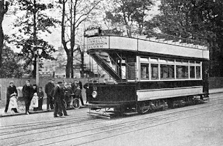
Fig. 4. Photograph of a car on a conduit section of
the London County Council tramways. The centre line on the vacant track
indicates the slot rail through which the 'plough' on the car passes to
make contact with the conductors in the underground conduit. (Photograph
reproduced by courtesy of Dick, Kerr and Company, Ltd.)
By ADAM GOWANS WHYTE, B.Sc.


Comments
Post a Comment