CURIOSITIES OF ELECTRIC TRACTION
Like many other industries, electric traction has had its history
brightened and made picturesque by curiosities of invention. Locomotion
has, in fact, been a favourite field for the freak inventor; and some of
his efforts with electric cars have been as weird and as fatuous as the
most remarkable of perpetual motion devices.
One of these electrical monstrosities was, indeed, a kind of perpetual motion arrangement. It was invented about the year 1890 and consisted of a car equipped with accumulators which supplied power to a motor which drove a hydraulic pump, which in turn worked a dynamo supplying current to motors driving the axles of the car, and also to the accumulator for re-charging purposes. The inventor was so sure that he had got the better of the law of the conservation of energy that he provided his car with pointed ends, fitted with revolving fans to break down the air-pressure, in order that a speed of 125 miles per hour might be achieved. His name was Amen; and it provides a fitting comment upon his scheme.
Several electric flying-machine ideas found their way on to the patent records. In 1893 a Frenchman registered a design for an air-ship with a cigar-shaped body and electrically-driven propellers. There was, however, more originality in an American idea that the progress of trains on the overhead railway might be assisted by the action of balloons in taking the weight of the cars off the rails. Curiously enough, other original inventors tried to get the opposite effect, by devising magnetic arrangements to increase the adhesion of the wheels to the rails.
More plausible forms of super-ingenuity have been exercised in connection with established modes of electric traction.
For the conduit system one inventor suggested a kind of reversion to the 'continuous valve' of the old atmospheric railway. The slot of the conduit was closed by a continuous series of springs which would be opened in succession by the plough as it passed along. This arrangement was actually tried on an experimental track in London. Another inventor proposed a novel plan for keeping the conductor in a conduit free from damp. The conductor was to be made hollow, so that hot air could be pumped through it to dry off any accumulated moisture.

The most entertaining freak in connection with the trolley system was a device to enable two lines of car to use a single trolley wire. Cars going in one direction were to carry a double-ended inclined plane which would lift the trolley wheels of passing cars off the wire and let them slip back again. The only drawback to this arrangement was that it would not work.
Another inventor who was apparently impressed with the noise of trolley wheels on the wires designed a trolley head fitted with a pneumatic tyre. If he could have persuaded indiarubber to be anything but one of the best of insulators, he would have been completely successful.
One of the best known of electrical freaks—the Heilmann locomotive (Fig. 14)—is a very good example of the way in which an invention may be tried with enthusiasm, rejected with contumely, and revived at a much later date in an improved and more promising form. The Heilmann locomotive was practically a generating station on wheels. It carried a boiler and engines, which drove a dynamo, the current from which was led through controllers to motors coupled to the wheel axles. It was an enormous affair, over 18 metres long and running on sixteen wheels; extensive trials were made with it on the Western Railway of France in the early nineties. Some advantage was gained in smoothness of running, ease and uniformity of control, and improved acceleration; but its great weight, cost, and complexity were against it. In spite of the cordial support given to it by railway engineers, it was soon relegated to the scrap-heap.

The Heilmann locomotive, it will be noticed, is similar in principle to the petrol-electric systems of propulsion now in use for road traction. But it is probable that the idea would never have been heard of again in connection with railway work had it not been for the appearance of the steam turbine. It was natural that the locomotive engineer should consider how the turbine could be applied to his purposes; and the first step in this inquiry made it plain that some electric method of control was necessary between the high-speed turbine and the driving axle.
Consequently, when the engineers of the North British Locomotive Company set to work in 1909 to design an 'electric turbo-locomotive,' they produced something not at all unlike the Heilmann locomotive. The equipment consists of a steam turbine, with elaborate condensing plant, a generator, and a group of driving motors (Fig. 15). The turbine runs at 3000 revolutions per minute and drives a continuous-current dynamo, the current from which passes through controllers to four motors which can be run in series, or two in series and two in parallel, or all in parallel, according to the draw-bar pull required. Trials with this locomotive were begun early in 1910, but it is yet too early to say whether it will be more fortunate than the Heilmann locomotive, and whether it is likely to delay the advance of the electric locomotive proper, fed with power by overhead wires from a central power station.

The possibilities of high speed on a mono-railway, and especially an electric mono-railway, have acted like a will-o'-the-wisp to the imaginations of many engineers. Of the various systems suggested, only one—the gyroscopic mono-railway invented by Mr Brennan—seems likely to survive; and even in that case victory under practical conditions is not yet certain.
At Ballybunnion there is a steam mono-railway which has been at work since 1888. It has had, so far as I am aware, no imitators; but its engineer, Mr Behr, retained so much faith in the principle that he decided to apply it to the problem of high-speed electric traction. During the 1900 session he promoted a Bill for the construction of a mono-railway between Liverpool and Manchester. There was tremendous opposition from the existing railway companies, which brought experts to prove that Mr Behr was a vain dreamer; but the Bill succeeded. The promoters, however, found it much harder work to raise capital for the project. They needed close upon £3,000,000, but the public response to the first invitation was so small that the scheme was abandoned.
The line, as projected, was nearly 35 miles long; and a speed of 100 miles per hour was intended, reducing the time of the Liverpool-Manchester journey to twenty minutes. At each end of the line (which was a double one) a steep gradient was arranged to facilitate starting and stopping—an arrangement, by the way, which is adopted to a certain extent on London tubes. The track itself was shaped like an inverted V, and practically the whole of the weight of the cars was borne upon a rail at the top. The wheels, therefore, were right in the centre of the car, which balanced itself on the trestle with its centre of gravity below the rail. Each side of the trestle carried two guide-rails which bore against free-running horizontal wheels on the car to prevent any undue lateral movement. Each car was designed to carry four motors with a total normal capacity of 160 horse power and an overload capacity up to 320 horse power. The rails for carrying the current were placed on the track in very much the same position as the ordinary rails occupy on a normal railway.
In another form of mono-railway—the Kearney high-speed railway—the wheels are placed below the car and run on a single rail laid direct on sleepers. The cars are held upright by flanged wheels on the top, running on a rail fixed to the roof of tunnels or to standards not unlike those of an overhead trolley. This railway has been exhibited in the form of a model.
Mr Brennan's gyroscopic mono-railway was first shown, in a small size, at a conversazione of the Royal Society in 1907. Full-sized cars were constructed later, and one was seen at work during the Japan-British Exhibition of 1910. The distinguishing feature of the vehicle is the use of two gyroscopes (electrically driven), one horizontal and the other vertical, to maintain the car upright on a single rail, even when loaded unevenly and running at a fair speed round sharp curves. From one point of view, the gyroscopic car is no more wonderful than a spinning top, but the spectacle of a vehicle running steadily on a single rail was so extraordinary that the interest of the whole world was immediately aroused. Support was given to Mr Brennan's experiments by the India Office and the Colonial Office, on the ground that a railway which required only one rail, and was more or less independent of both curves and gradients, would be of great value in districts where the ordinary two-track railway might be both inconvenient and too costly. One drawback to the arrangement is the necessity of fitting each vehicle with gyroscopes, which are expensive and delicate pieces of apparatus. But the ingenuity of the invention is so great that Mr Brennan ought to reap the reward of seeing a gyroscopic railway in full operation before long.

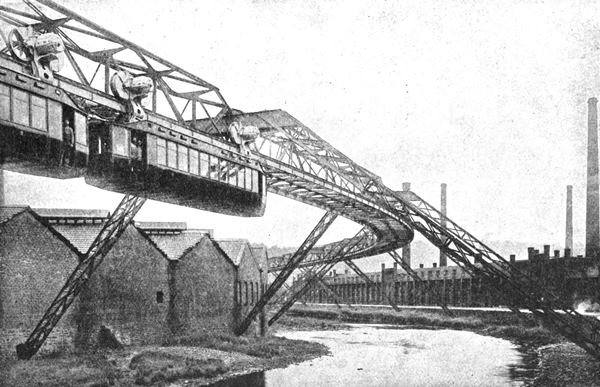
The only electric mono-railway actually at work is the 'hanging railway' at Elberfeld in Germany (Fig. 13).
This railway is an evolution from the system of 'telpherage' which was
devised in the very infancy of electric traction for the transport of
goods. The root idea is to make the overhead wire carrying the current
the track rail as well, the whole contrivance—rails and cars—being
suspended from girders or cables
supported by a series of standards or bridges. At Elberfeld the cars
pass over streets and also over canals. There are no signs, however,
that the 'hanging railway' will have any imitators. In appearance and in
cost of construction and operation it does not seem to have any
conspicuous advantages over a double-track overhead railway. The system
of telpherage is therefore likely to be confined to the carriage of
goods from one part of a factory to another, and (in the form of
cable-ways) to the handling of materials in mines and other extensive
engineering works. For such purposes it is having an increasingly
extended application.
One of these electrical monstrosities was, indeed, a kind of perpetual motion arrangement. It was invented about the year 1890 and consisted of a car equipped with accumulators which supplied power to a motor which drove a hydraulic pump, which in turn worked a dynamo supplying current to motors driving the axles of the car, and also to the accumulator for re-charging purposes. The inventor was so sure that he had got the better of the law of the conservation of energy that he provided his car with pointed ends, fitted with revolving fans to break down the air-pressure, in order that a speed of 125 miles per hour might be achieved. His name was Amen; and it provides a fitting comment upon his scheme.
Fig. 13. Illustration of Elberfeld-Barmen hanging electric railway. From The Electrical Industry (Books on Business), published by Messrs Methuen.
Several electric flying-machine ideas found their way on to the patent records. In 1893 a Frenchman registered a design for an air-ship with a cigar-shaped body and electrically-driven propellers. There was, however, more originality in an American idea that the progress of trains on the overhead railway might be assisted by the action of balloons in taking the weight of the cars off the rails. Curiously enough, other original inventors tried to get the opposite effect, by devising magnetic arrangements to increase the adhesion of the wheels to the rails.
More plausible forms of super-ingenuity have been exercised in connection with established modes of electric traction.
For the conduit system one inventor suggested a kind of reversion to the 'continuous valve' of the old atmospheric railway. The slot of the conduit was closed by a continuous series of springs which would be opened in succession by the plough as it passed along. This arrangement was actually tried on an experimental track in London. Another inventor proposed a novel plan for keeping the conductor in a conduit free from damp. The conductor was to be made hollow, so that hot air could be pumped through it to dry off any accumulated moisture.
Fig. 14. The Heilmann electric locomotive—a
generating station on wheels. The general arrangement of this locomotive
should be compared with that of the modern electric turbo-locomotive
described and illustrated in Fig. 15.
The most entertaining freak in connection with the trolley system was a device to enable two lines of car to use a single trolley wire. Cars going in one direction were to carry a double-ended inclined plane which would lift the trolley wheels of passing cars off the wire and let them slip back again. The only drawback to this arrangement was that it would not work.
Another inventor who was apparently impressed with the noise of trolley wheels on the wires designed a trolley head fitted with a pneumatic tyre. If he could have persuaded indiarubber to be anything but one of the best of insulators, he would have been completely successful.
One of the best known of electrical freaks—the Heilmann locomotive (Fig. 14)—is a very good example of the way in which an invention may be tried with enthusiasm, rejected with contumely, and revived at a much later date in an improved and more promising form. The Heilmann locomotive was practically a generating station on wheels. It carried a boiler and engines, which drove a dynamo, the current from which was led through controllers to motors coupled to the wheel axles. It was an enormous affair, over 18 metres long and running on sixteen wheels; extensive trials were made with it on the Western Railway of France in the early nineties. Some advantage was gained in smoothness of running, ease and uniformity of control, and improved acceleration; but its great weight, cost, and complexity were against it. In spite of the cordial support given to it by railway engineers, it was soon relegated to the scrap-heap.
Fig. 15. Electro-turbo-locomotive built by the North
British Locomotive Company for experimental purposes. This locomotive
is a 'generating station on wheels.' It carries a steam turbine driving a
dynamo which supplies current through a controller to motors geared to
the axles.
The Heilmann locomotive, it will be noticed, is similar in principle to the petrol-electric systems of propulsion now in use for road traction. But it is probable that the idea would never have been heard of again in connection with railway work had it not been for the appearance of the steam turbine. It was natural that the locomotive engineer should consider how the turbine could be applied to his purposes; and the first step in this inquiry made it plain that some electric method of control was necessary between the high-speed turbine and the driving axle.
Consequently, when the engineers of the North British Locomotive Company set to work in 1909 to design an 'electric turbo-locomotive,' they produced something not at all unlike the Heilmann locomotive. The equipment consists of a steam turbine, with elaborate condensing plant, a generator, and a group of driving motors (Fig. 15). The turbine runs at 3000 revolutions per minute and drives a continuous-current dynamo, the current from which passes through controllers to four motors which can be run in series, or two in series and two in parallel, or all in parallel, according to the draw-bar pull required. Trials with this locomotive were begun early in 1910, but it is yet too early to say whether it will be more fortunate than the Heilmann locomotive, and whether it is likely to delay the advance of the electric locomotive proper, fed with power by overhead wires from a central power station.
Fig. 16. Diagrammatic sections of the Behr electric
mono-rail car. The car is balanced on the summit of a continuous trestle
and is designed for speeds up to 120 miles per hour.
The possibilities of high speed on a mono-railway, and especially an electric mono-railway, have acted like a will-o'-the-wisp to the imaginations of many engineers. Of the various systems suggested, only one—the gyroscopic mono-railway invented by Mr Brennan—seems likely to survive; and even in that case victory under practical conditions is not yet certain.
At Ballybunnion there is a steam mono-railway which has been at work since 1888. It has had, so far as I am aware, no imitators; but its engineer, Mr Behr, retained so much faith in the principle that he decided to apply it to the problem of high-speed electric traction. During the 1900 session he promoted a Bill for the construction of a mono-railway between Liverpool and Manchester. There was tremendous opposition from the existing railway companies, which brought experts to prove that Mr Behr was a vain dreamer; but the Bill succeeded. The promoters, however, found it much harder work to raise capital for the project. They needed close upon £3,000,000, but the public response to the first invitation was so small that the scheme was abandoned.
The line, as projected, was nearly 35 miles long; and a speed of 100 miles per hour was intended, reducing the time of the Liverpool-Manchester journey to twenty minutes. At each end of the line (which was a double one) a steep gradient was arranged to facilitate starting and stopping—an arrangement, by the way, which is adopted to a certain extent on London tubes. The track itself was shaped like an inverted V, and practically the whole of the weight of the cars was borne upon a rail at the top. The wheels, therefore, were right in the centre of the car, which balanced itself on the trestle with its centre of gravity below the rail. Each side of the trestle carried two guide-rails which bore against free-running horizontal wheels on the car to prevent any undue lateral movement. Each car was designed to carry four motors with a total normal capacity of 160 horse power and an overload capacity up to 320 horse power. The rails for carrying the current were placed on the track in very much the same position as the ordinary rails occupy on a normal railway.
In another form of mono-railway—the Kearney high-speed railway—the wheels are placed below the car and run on a single rail laid direct on sleepers. The cars are held upright by flanged wheels on the top, running on a rail fixed to the roof of tunnels or to standards not unlike those of an overhead trolley. This railway has been exhibited in the form of a model.
Fig. 17. The Brennan gyroscopic mono-railway.—The
car is electrically driven, and its equilibrium is maintained by the
action of two gyroscopes, also electrically driven.
Mr Brennan's gyroscopic mono-railway was first shown, in a small size, at a conversazione of the Royal Society in 1907. Full-sized cars were constructed later, and one was seen at work during the Japan-British Exhibition of 1910. The distinguishing feature of the vehicle is the use of two gyroscopes (electrically driven), one horizontal and the other vertical, to maintain the car upright on a single rail, even when loaded unevenly and running at a fair speed round sharp curves. From one point of view, the gyroscopic car is no more wonderful than a spinning top, but the spectacle of a vehicle running steadily on a single rail was so extraordinary that the interest of the whole world was immediately aroused. Support was given to Mr Brennan's experiments by the India Office and the Colonial Office, on the ground that a railway which required only one rail, and was more or less independent of both curves and gradients, would be of great value in districts where the ordinary two-track railway might be both inconvenient and too costly. One drawback to the arrangement is the necessity of fitting each vehicle with gyroscopes, which are expensive and delicate pieces of apparatus. But the ingenuity of the invention is so great that Mr Brennan ought to reap the reward of seeing a gyroscopic railway in full operation before long.
Fig. 18. The 'Telpher' system of electrical
locomotion adapted to the transport of materials in a factory. The 'car'
is suspended from a girder and is operated by the driver in the same
way as an electric car. (From Electrics.)
By ADAM GOWANS WHYTE, B.Sc.


Comments
Post a Comment